auf LIFEPO4 umrüsten > nur f. Expert Arnoldfreunde
Understanding LiFePO4 BMS. A BMS or battery management system is an important part of any lithium-ion battery system. You can think of it as the brains of your system. It essentially makes sure your battery stays healthy by controlling the discharge and charging process. In addition, it also monitors the battery cells and measures parameters.

BMS 120a 4s LifePo4 Battery Management System for 12v DIY Batteries, Programmable, Bluetooth
Lifepo4 Bms Schaltplan Here are some general guidelines for configuring a BMS for a LiFePO4 battery: Voltages. Charge voltage: The charge voltage for a LiFePO4 battery should typically be set to around 3.6 volts per cell. This will ensure that the battery is charged to its full capacity while minimizing the risk of overcharging, which can damage the battery.
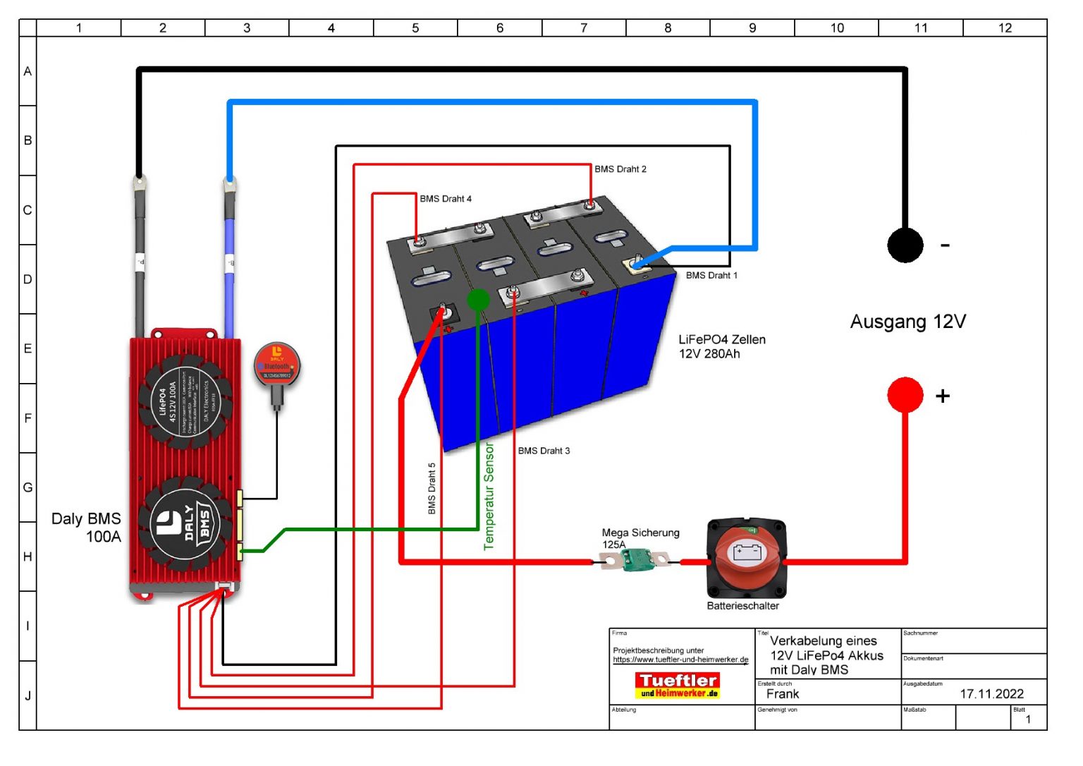
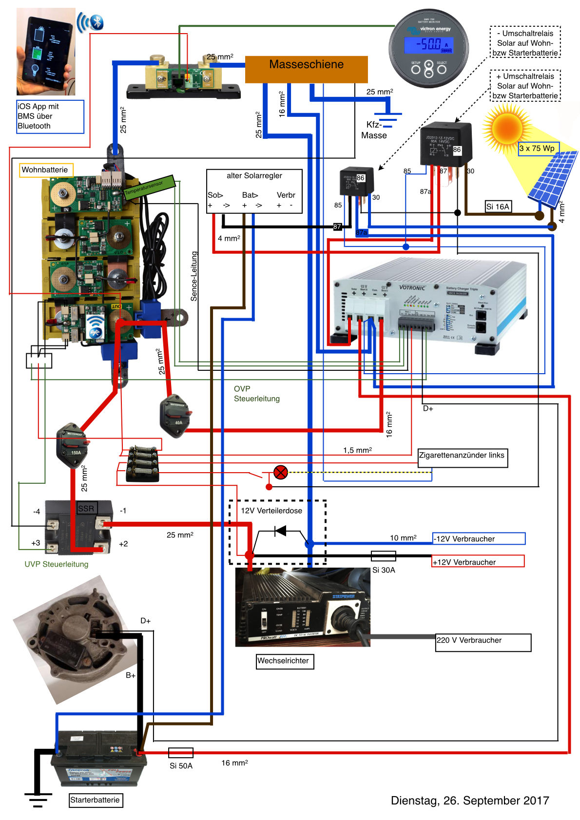
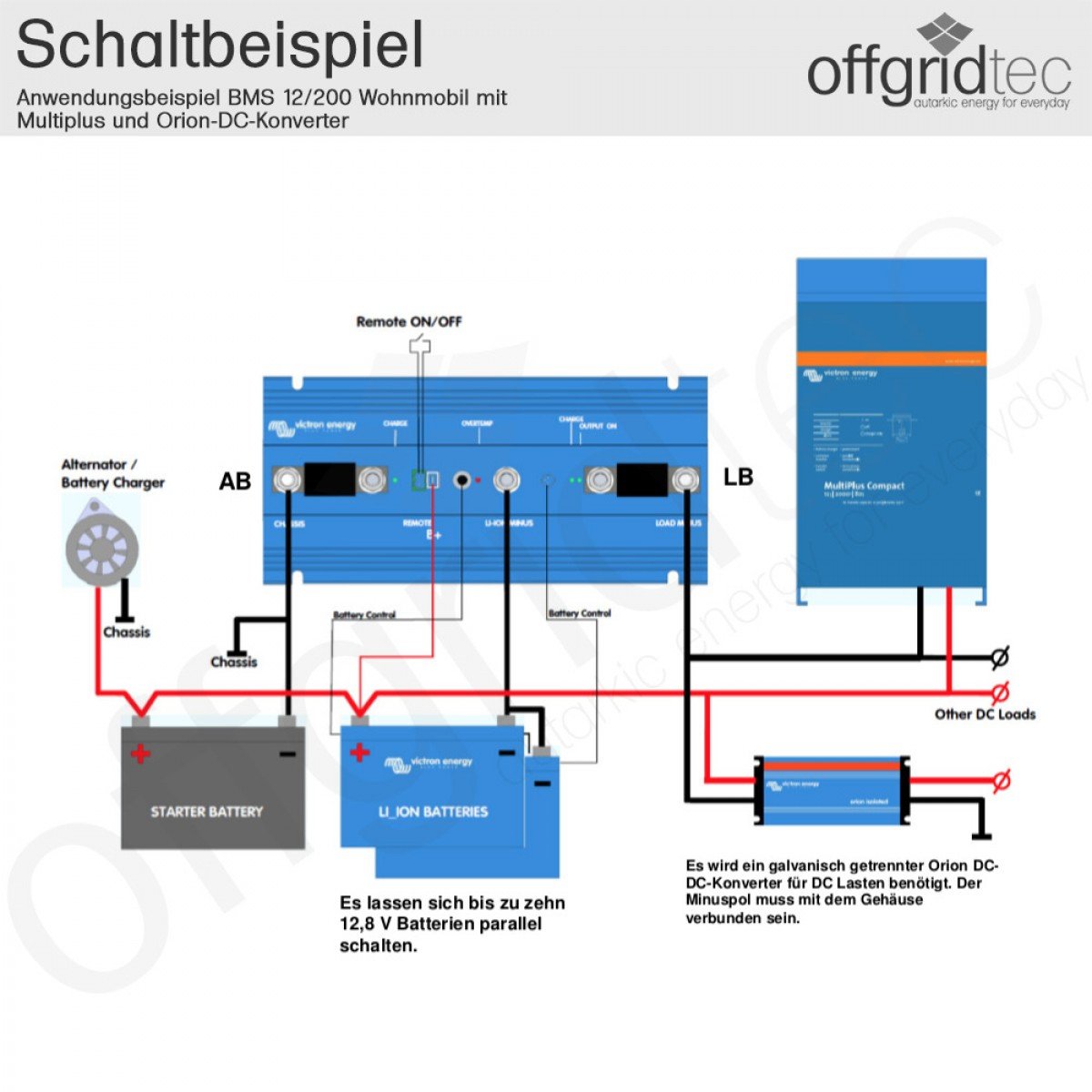
12V LiFePO4Akku Verkabelung Schaltplan TueftlerundHeimwerker.de
A LiFePO4 BMS controls the discharge and charge processes of LiFePO4 battery packs. So if anything goes wrong during these processes, the BMS protection immediately kicks in and adjusts the charging parameters or cuts off the power flowing to and from the battery pack entirely.

Victron Energy Lithium LiFePO4 Akku 12V f. BMS Off Grid Solar Power, Rv Lighting, Dc Dc
LiFePO4 Voltage Settings guide for BMS, Chargers and Loads 2022-04-09 Download FilterGuy Dec 3, 2020 Overview Reviews (7) History To get the document, click on the orange button at the top of the page. All the voltage settings in the BMS, Loads and Chargers can be daunting to figure out.
Lifepo4 12V BMS sperrt Ladung, Entladung funktioniert Wohnmobil Forum Seite 1
Here are some general guidelines for configuring a BMS for a LiFePO4 battery: Voltages Charge voltage: The charge voltage for a LiFePO4 battery should typically be set to around 3.6 volts per cell. This will ensure that the battery is charged to its full capacity while minimizing the risk of overcharging, which can damage the battery.

Cerbo GX, VE.Bus BMS, LiFePO4, Multi Victron Community Setup, Alternator, Sailing yacht
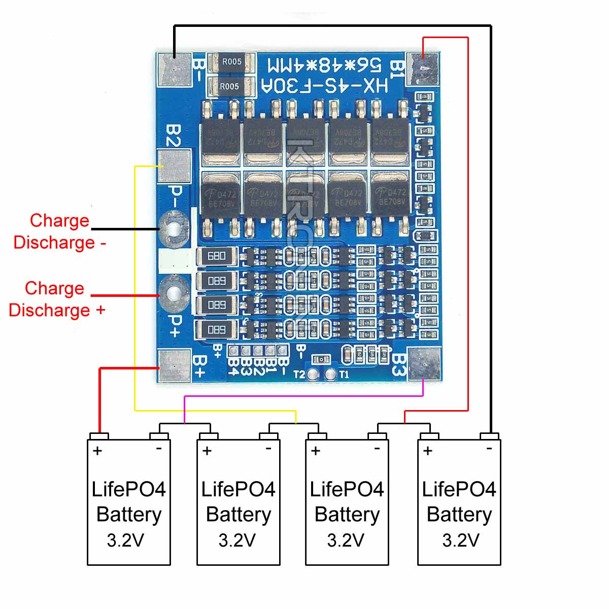
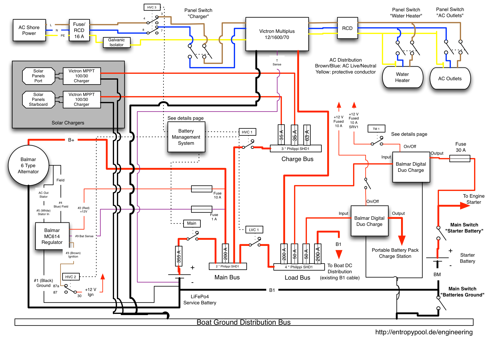
A LiFePO4 BMS circuit diagram is a graphical representation of a LiFePO4 battery and its associated components. It serves as a guide for the correct wiring and connections between the battery, controller, and other components.
4S 30A Battery Management System ( BMS ) LifePO4 roboway
2020-12-10. All the voltage settings in the BMS, Loads and Chargers can be daunting to figure out. This paper attempts to explain the various settings, how they relate to each other and how to choose them. A big shout-out to @Dzl for helping develop this resource. As with all of the resources I create, reviews, comments, suggestions and.

EREMIT LiFePO4 BMS Schutzschaltung
LiFePO4 . Nominal Voltage 12V 12V 12V 12.8V Charging Voltage 14 14.6 14.8 14.4-14.6 Life Cycles @ 50% DOD >4000 . 500-600 cycles 500-600 cycles 500-600 cycles cycles- no DOD recommended Constant Output Voltage No No No Yes Operating Temperature -4° F to 140° F -4° F to 140° F -4° F to 122° F -4° F to 149° F BMS No No No Yes
Destillieren Meeresschnecke Maori lifepo4 mit agm parallel schalten Abkürzung Keim Ansager
First, connect your battery to the BMS. Make sure the connection is secure and make sure the power is turned off on the battery. Then, turn on the power to the BMS. Next, configure the BMS to use the battery. The BMS will need information about the type of battery and the amount of power it needs.

Lifepo4 Bms Schematic Daniel Stine Schaltplan
JBD Smart BMS 8S 16S 6~10S 60A 80A 100A Lifepo4 Li-ion for Lithium Iron Battery Pcb with UART RS485 Function/BT Module with Balance Wires. $63.76 USD From $59.64 USD. Sale.
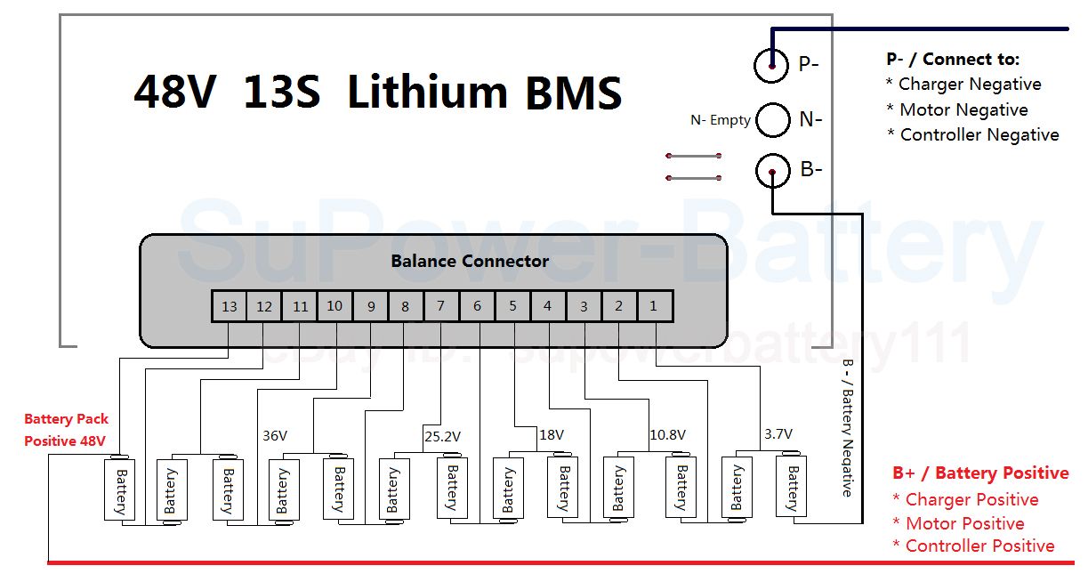
16s Lifepo4 Bms Wiring Diagram
LiFePo4 Power System from Shenzhen Lith Battery. Read all installation instructions prior to installation of the LITH-BMS. 1. SAFETY INFORMATION The BMS (Battery Management System) must be used in accordance with the manufacturer's specifications and guidelines for recommended use.
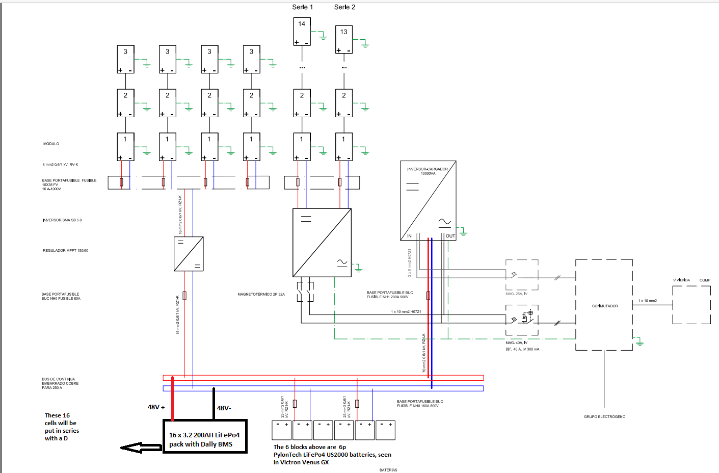
Lifepo4 Bms Circuit Diagram Wiring Diagram
LifePO4 BMS units are designed specifically for the lower nominal voltage, flat discharge curve and thermal stability of lithium iron phosphate cells. This allows simpler charge/discharge management and avoids issues like lithium plating. LifePO4 BMS can use passive balancing since the cells stay balanced naturally.
BMS abändern
Malaysia. Vehicle: 2012 Prius. Model: N/A. I have successfully built a 12v lifepo4 battery with 50aH. 4s x lifepo4 cells of 50ah each. EVE brand cell. I have a BMS rated at 100A supposedly able to work on cars with cranking amp requirement. This part is a bit iffy if you know how cheap parts from China always exaggerate it's ratings.

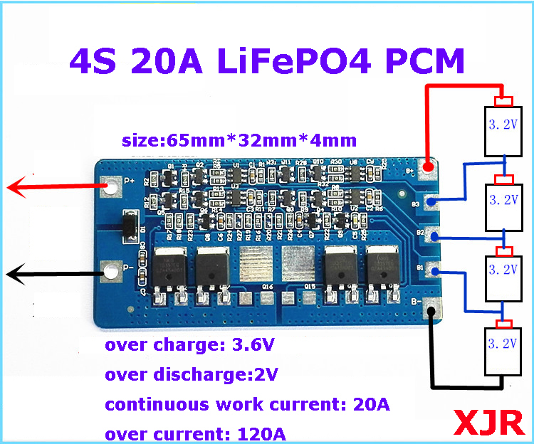
Liion/LiPo Protection circuit (BMS) 4S with Balancing BMS4S30A
And to charge the 110Ah battery bank, the charging current the BMS module must be able to withstand should be at least 6A (at C/20 rate). Based on these requirements, I found this 4S LiFePO4 BMS module on eBay (see pictures below). It is rated for a continuous discharge current of 100A and has a maximum charge current of 10A which is perfect.

Ellen Schaltplan Lifepo4 Bms Schaltplan
Again, for my BattleBorn LiFePO4, if the BMS shuts down due to discharge, you "jump" it for a moment to reset the BMS. If the BMS shuts down due to overcharging, it will show just under 12 volts and not accept any further current. In that state, I must place a load on the battery. For my battery, a 1.5 to 2.0 amp load will turn the BMS back on.
Lifepo4 Bms Circuit Diagram Wiring Diagram
You can calculate the BMS (Battery Management System) for Lithium Iron Phosphate (LiFePO4 or LFP) batteries by dividing the nominal voltage that your project needs by 3.25, which is the nominal voltage of LiFePO4 chemistry, and rounding to the nearest whole number. NMC vs LifePO4 Voltages
