
Spotting The Correct Earthing Arrangement Either TNS or TNCS in a Single Phase Domestic
626 Share Save 25K views 2 months ago ELECTRICIANS' TECHNICAL Q&A Understanding the earthing system used in electrical installations is essential. Joe Hammond's video provides a detailed.

Engineering Boy Types Of Earthing System
Types of Earthing Systems - What is TT, IT & TN Earthing? The 3 major types of Earthing Systems used by IEC 60364 are TT , IT, TN - TN-S, TN-C, TN-C-S Earthing System.

How to create a specific neutral earthing system within existing one (islanding) EEP
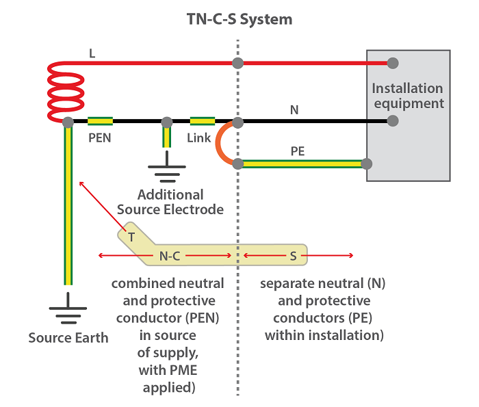
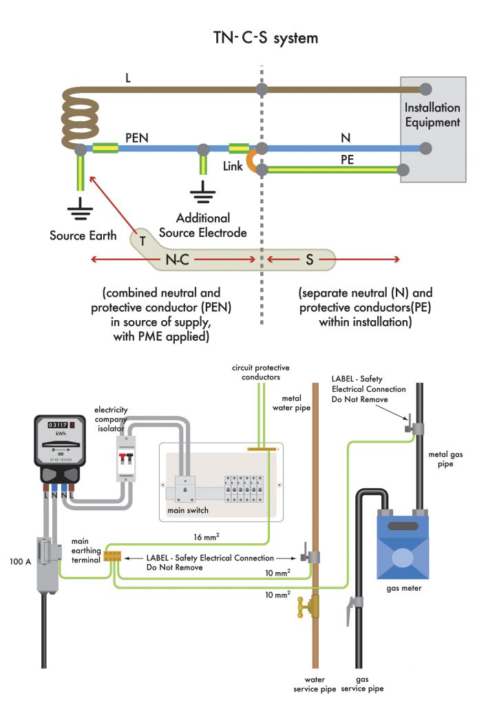
In the UK and before the introduction of protective multiple earthing (PME or TN-C-S) systems, the TN-S method was pretty much the standard arrangement. TN-C-S In this method, the supply cables have a combined neutral and earth metallic outer sheath with a PVC covering. The combined neutral earth sheath is the PEN (protective earth neutral).

TNCS Earthing System Definition, Meaning, Diagrams Asutpp
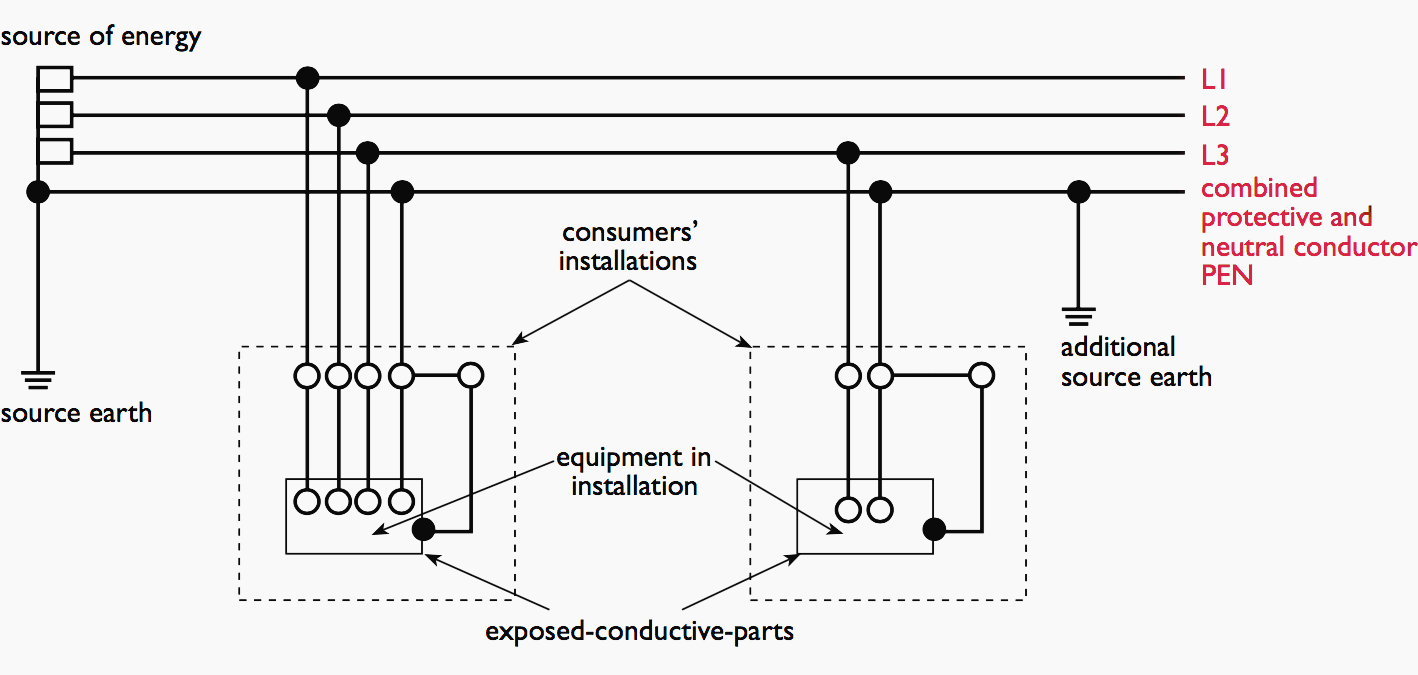
TN earthing system. A single point on the source side (usually the neutral reference point in a star-connected three-phase system) is directly connected to earth. Any electrical equipment connected to the system is earthed via the same connection point on the source side. These type of earthing systems require earth electrodes at regular.
TNCS Earthing System Diagram, Advantages, Features Linquip
To sum up, TNS and TNCS are two distinct earthing systems that differ in how they connect the neutral and earth conductors. The TNS system has a separate earth conductor, while the TNCS system combines the neutral and earth conductors into a single core. Conclusion. TN-S is a reliable and safe earthing system used in electrical installations.

TNS Earthing System Explanation, Advantages, Diagrams Asutpp
System earthing serves a purpose of electrical safety throughout the system that is not caused by an electrical fault. Its main purpose is to prevent static buildup and to protect against power surges caused by nearby lightning strikes or switching. [2]

CHAPTER 6 EARTHING SYSTEM CHAPTER 6 EARTHING
The TN-C system requires an effective equipotential environment within the installation with dispersed earth electrodes spaced as regularly as possible. It is because the PEN conductor is both the neutral conductor and at the same time carries phase unbalance currents as well as third-order harmonic currents (and their multiples).
TNCS Earthing System Diagram, Advantages, Features Linquip
The neutral and the earthed parts are only connected together via an electrode system back to the source earth (and neutral).

Types of Earthing eereco
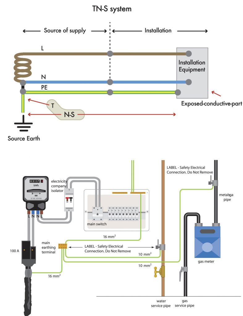
The TN-S mode power supply system is a power supply system that strictly separates the working neutral N from the dedicated protection line PE. It is called the TN-S power supply system. TT power supply system
TNS Earthing System Characteristic of TNS, Diagram Linquip
A brief and simple explanation of the TN-S earthing system and how to recognise it. This will be useful to students on level 2 and 3 electrical installation.

An introduction to earthing and bonding
TN-S Earthing System (or TN-S system): a distribution system in which one live part of a power source is earthed, exposed-conductive-parts of an electrical installation are connected to the earthed live part of the power source by protective earthing conductors (PE) [this term is defined in the IEC 60364-1].
The essentials of electric shock protection, earthing systems and RCDs
In the TNS earthing system, there is an earth terminal at the incoming mains position. This earth terminal is connected by the supply protective conductor (PE) back to the start point (neutral) of the secondary winding of the supply transformer, which is also connected at that point to an earth electrode.
An introduction to earthing and bonding
This video provides an understanding of the design of LV power system earthing arrangements (TT and TN-S system). It provides insights into the bonding requi.
Earthing Systems
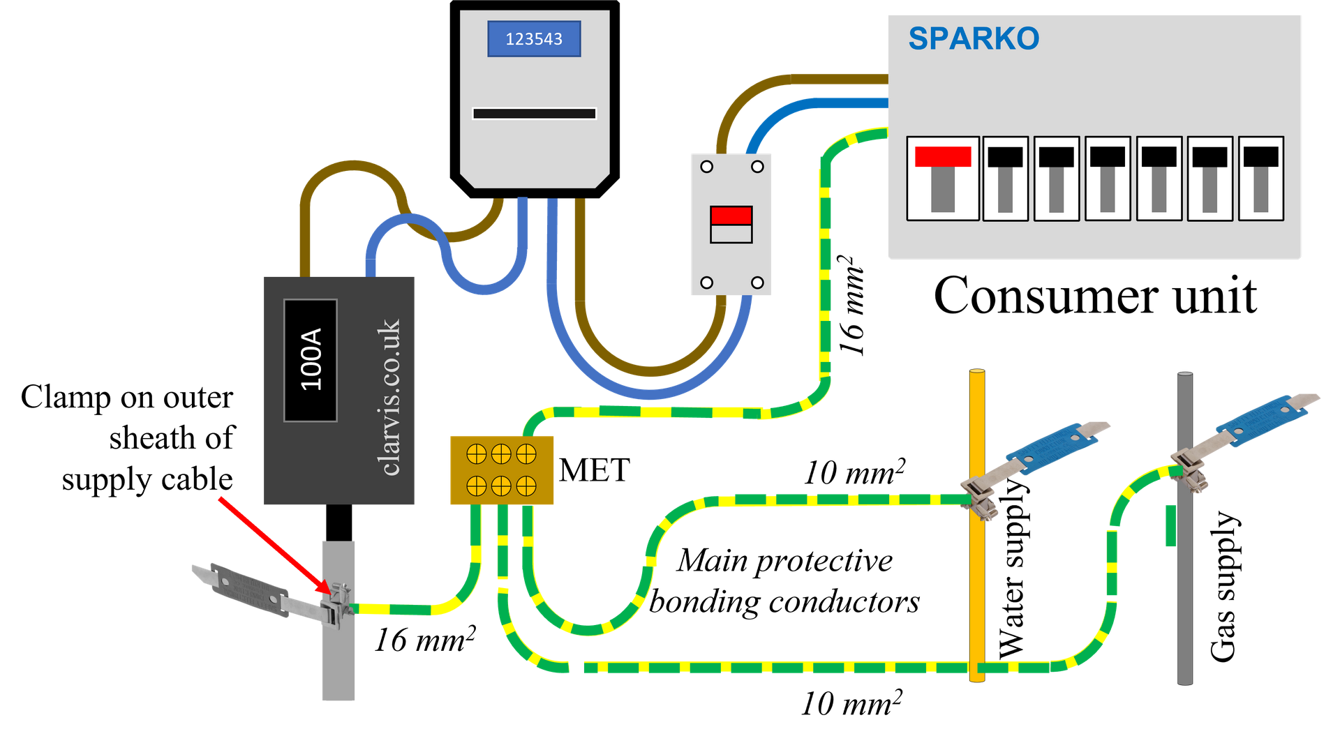
dedicated power transformer on the construction site, the TNS earthing system must be used. TNCS earthing system diagram The Neutral and Earth wires are combined within the supply cable. Typically this will be a concentric cable, with the line as the central core, and a ring of wires around this for the combined neutral and earth.

Recap of TNCS Earthing Arrangements and Measuring External Earth Fault Loop Impedance Ze YouTube
This method summates the positive-sequence impedances of each item (cable, PE conductor, transformer, etc.) included in the earth-fault loop circuit from which the earth-fault current is calculated, using the formula: I = U 0 ( ∑ R) 2 + ( ∑ X) 2. where. U0 = nominal system phase-to-neutral voltage. (ΣR)2 = (the sum of all resistances in.
An introduction to earthing and bonding
What is TNS Earthing System? We've explained TNS Earthing System in detail including its components, benefits and comparison with TN-C, TN-C-S, and IT systems.
