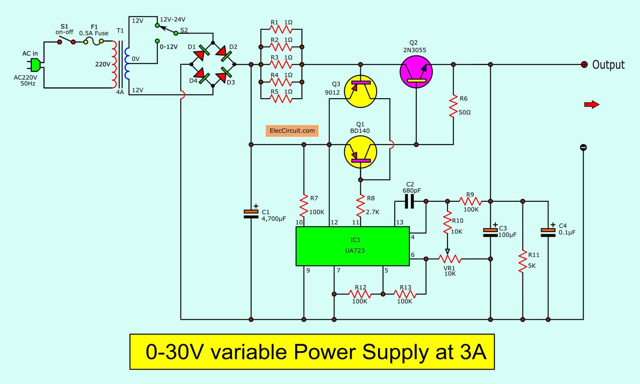
030V Variable Power Supply Circuit Diagram / 030V 05A regulated variable power supply circuit
Favorite 53 Overview One of the key concepts in electronics is the printed circuit board or PCB. It's so fundamental that people often forget to explain what a PCB is. This tutorial will breakdown what makes up a PCB and some of the common terms used in the PCB world.
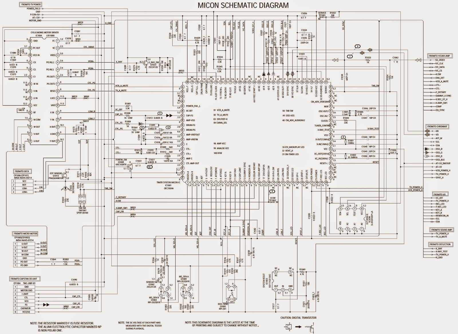
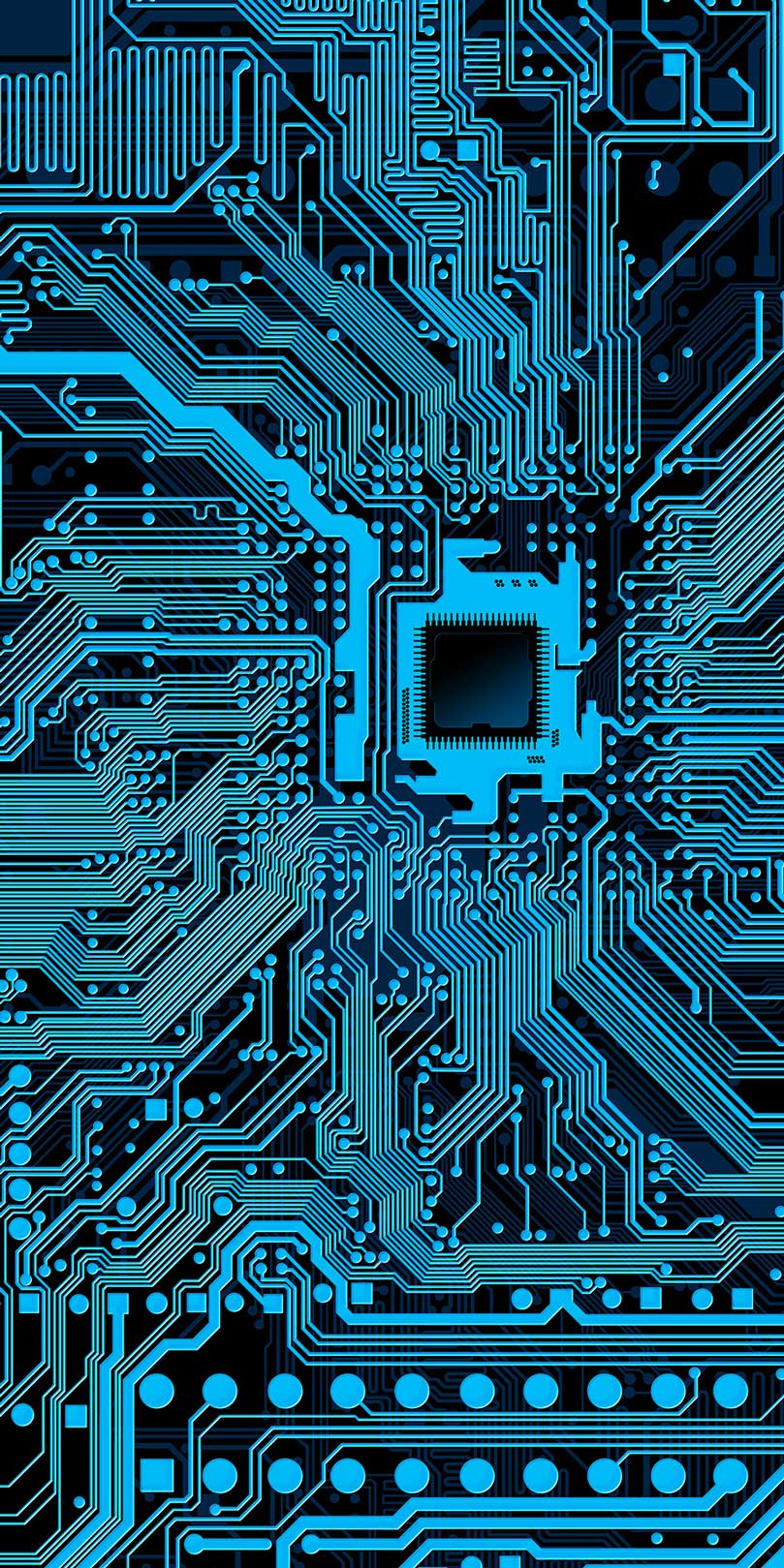
Schematic Diagram Circuit Board
Our archive has gather some thousands of circuits. This would require a significant amount of disk space. 3. PCB Heaven circuits archive is a the librarian, not the library. This means that our intention is to find, categorize and help you discover the circuit you want. We do not intent to copy and keep it as a library that keeps all books.
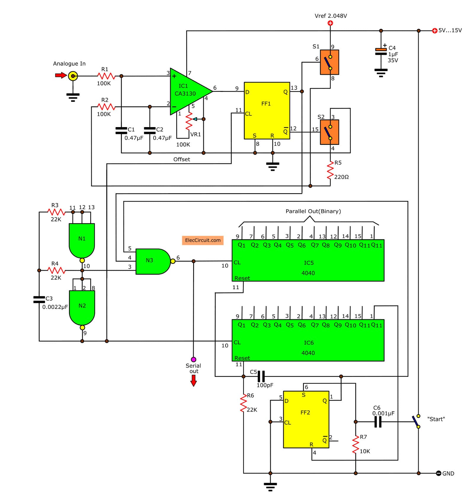
Analog To Digital Converter Circuit
An electrical schematic is a diagram that shows how all of the wires and components in an electronic circuit are connected. They're like a map for building or troubleshooting circuits, and can tell you almost everything you need to know to understand how a circuit works. The ability to read electrical schematics is a really useful skill to.

Printed Circuit Board Lying On Diagram Of Electronics Technology Stock Photo Download Image
A substantial difference between the PCB schematic and layout is that a schematic is the first diagram drawn in the process of PCB designing. It contains 2-dimensional lines that arrange all the components connecting in an organized manner. On the other hand, a PCB layout is like a virtual circuit board that is okay to consider as a digital.
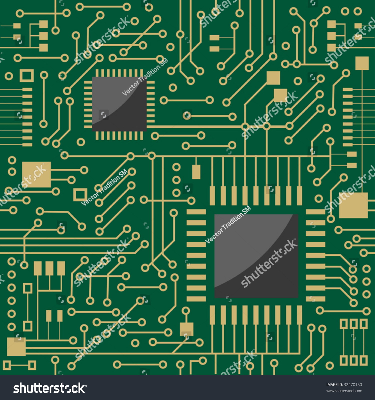
Seamless Background Showing A Schematic Diagram For An Electronic Circuit Board Or Motherboard
Circuit board schematics are visual representations of electronic circuits, depicting the connections between components such as resistors, capacitors, integrated circuits, and more. These schematics are essential for designing, prototyping, and manufacturing electronic devices, from simple gadgets to complex systems..
8051 Development System Circuit Board
Schematics detail the circuitry that is built into and installed on a printed circuit board. Originally hand-drawn on a drafting table, schematics are now created using computer-aided design tools.
Circuit Board Free Stock Photo Public Domain Pictures
The Basic Schematic A schematic consists primarily of components and wires connected in such a way as to produce the desired electrical behavior. The wires will become traces or copper pours.
12+ Circuit Board Schematic Robhosking Diagram
Common sense schematics let you name a node "+5V" and know that the simulator will do the right thing automatically, keeping your schematics compact and elegant. Quick-access build box lets you draw basic circuit primitives quickly, while allowing access to a wide assortment of non-linear elements, feedback elements, digital / mixed-mode.

Premium Template for PowerPoint & Google Slides (29271)
1. Take the device you're interested in learning more about. Note that not all electronics are required to have FCC certification, but odds are if it transmits, receives, or potentially emits RF in any way, it will have an FCC ID. 2. Find the FCC ID on the device. Sometimes this is in plain view on the back.

Printed Circuit Board Schematic Diagram Circuit Diagram
looks. These drawings show the actual layout of the components on the circuit board. This provides a two-dimensional drawing, usually looking down from the top, detailing the components in their location. Shown in Figure 4 is the schematic for a circuit and the same circuit drawn in pictorial or layout format for comparison. Normally the pictorial
If you have a schematic diagram or a circuit board, the best and easiest way to start analyzing it is from the power source. Every electronic component depends on some sort of power supply. Commonly the designing process of a circuit also begins from there. The most common type of failure in electronic devices is also power supply failure.
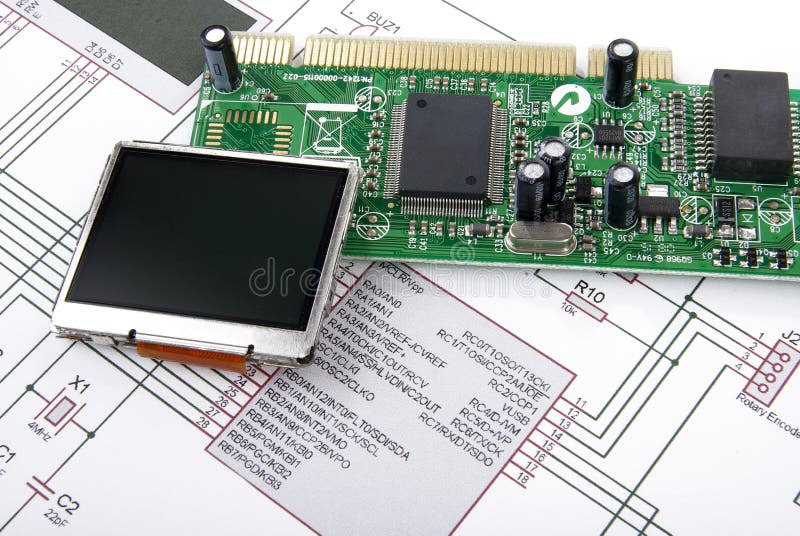
Display and Circuit Board with Schematic Stock Image Image of drawing, chip 12335645
1. Check the manufacturer's website. If you know the manufacturer of the circuit board, the first place you should look is on their website. Oftentimes, they will have schematics available for download. 2. Do a general search.

Circuit Board Free Stock Photo Public Domain Pictures
A circuit board schematic layout can be depicted as a circuit chart or a utilitarian graph of an electronic circuit. Images are used to speak to components and how they are electrically associated. Such PCB schematic designs are regularly made earlier than the simple plan format of the circuit.
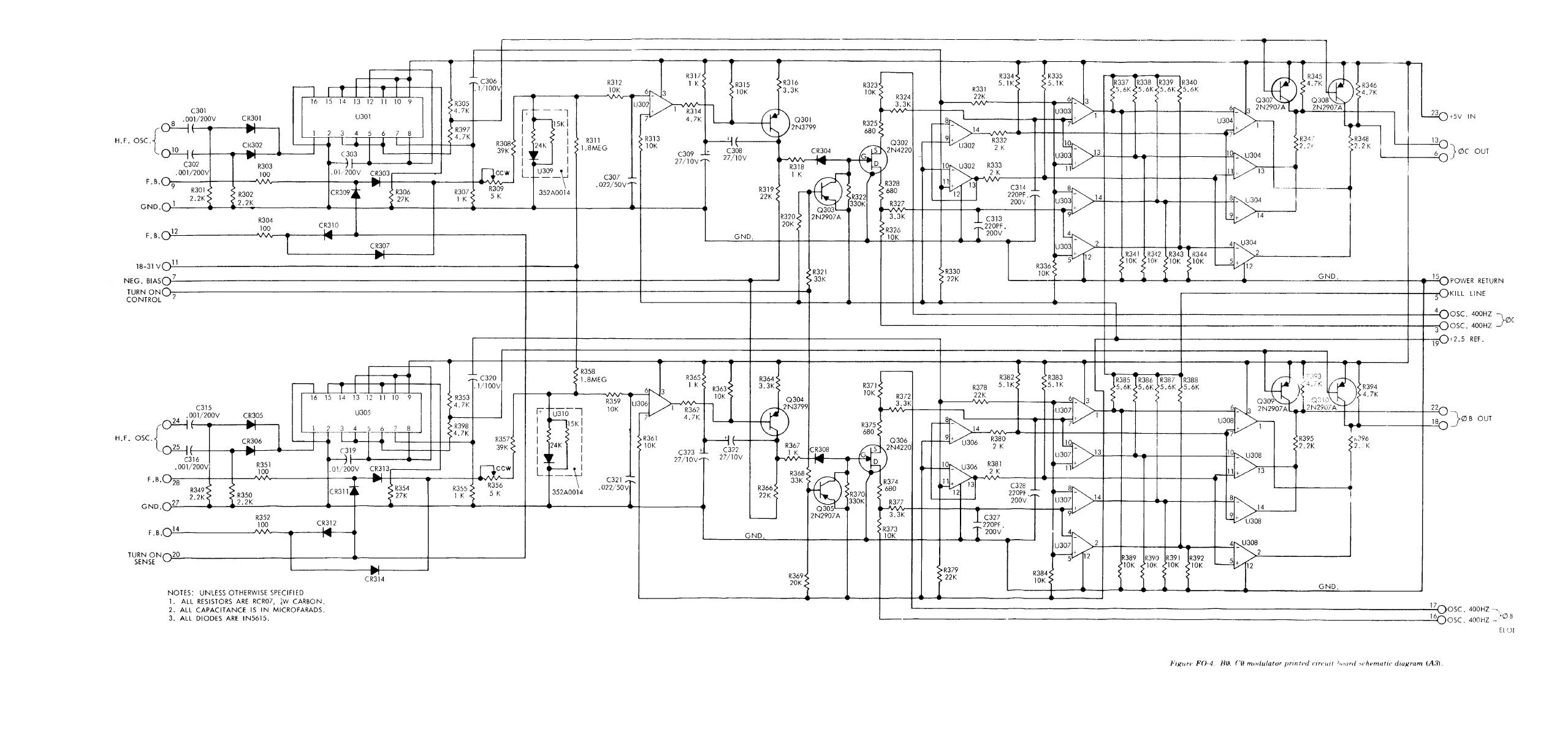
Figure FO4. B modulator and current sense printed circuit board schematic diagram (A3)
Circuit board schematic Schematics may range from the complex, with densely packed components, to quite simple with a single part such as an antenna. For the development of PCBAs, circuit board schematics are utilized as follows: 1. The platform for hatching a circuit design idea
Looking for a beginners guide to electrical stability in the home. r/electricians
A circuit diagram behind a circuit board. kr7ysztof / Getty Images. Schematic diagrams are typically associated with electrical circuits. Also called wiring diagrams or circuit diagrams, these diagrams show how the different components of a circuit are connected.In these diagrams, lines represent connecting wires, while other elements like resistors, lamps, and switches are represented by.

Premium Template for PowerPoint & Google Slides (29271)
43 8 Download By robmawe91 Follow More by the author: In this instructable I will talk about how to read a schematic and how to identify electrical components on a PCB (Printed Circuit Board). Electrical components are identified two main ways. Abbreviations Symbols.
