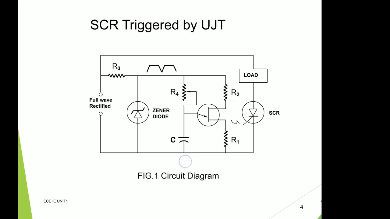
SCR TRIGGERING BY UJT, POWER CONTROL CIRCUIT USING DIAC AND TRIAC YouTube
A MAIN-ZERO TRIAC-TRIGGERING CIRCUIT jUNE 1976: celduc-relais: SG541020: 141Kb / 5P: RELAY WITH PROPORTIONAL CONTROL Festo Corporation. 539639: 88Kb / 2P: Proportional pressure control valve 1/21/22: 557772: 88Kb / 2P: Proportional pressure control valve 1/21/22: 557773: 87Kb / 2P: Proportional pressure control valve 1/21/22: 557777: 91Kb / 2P.
Simple Triac Triggering Circuits Explained Homemade Circuit Projects
This paper presents a comprehensive comparison of the phase control (PC) and time-proportional control (TPC) schemes, which are commonly used for power control of alternating current (AC) loads with alternating current triodes (TRIACs).

Ramp and Pedestal Triggering Circuit of SCR
A power controller device which uses a voltage-to-frequency converter in conjunction with a zero crossing detector to linearly and proportionally control AC power being supplied to a load. The output of the voltage to frequency converter controls the reset input of a R-S flip flop, while an 0 crossing detector controls the set input.

(PDF) TDA1024 Datasheet A MAINZERO TRIACTRIGGERING CIRCUIT
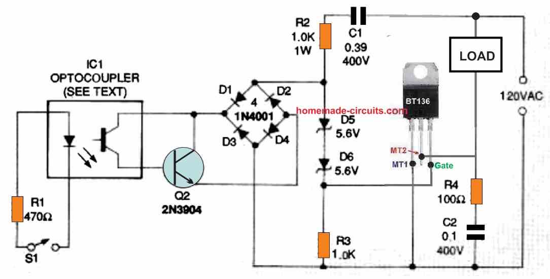
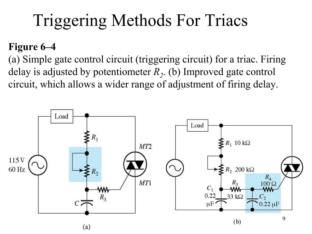
A triac is a three-terminal (MT1, gate, and MT2) solid-state thyristor that uses the alternative symbols in Figure 1 and acts like a pair of SCRs wired in inverse parallel and controlled via a single gate terminal. FIGURE 1. Triac symbols. It can conduct current in either direction between its MT1 and MT2 terminals and can thus be used to.

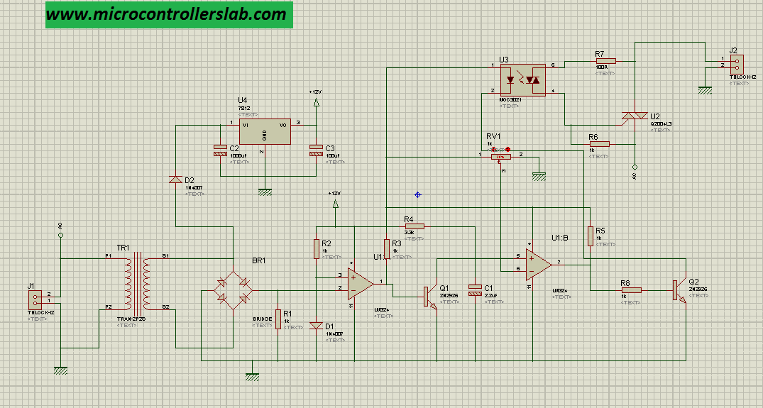
Triac Phase Control using PWM Time Proportional Circuit Electronic Circuit Projects
Proportional-control triac triggering circuit: Datasheet *) TDA1023: 13.7 V, proportional-control triac triggering circuit in 16-pin DIL package. Operational temperature range from -20 ° C to 75 ° C. Datasheet *) TDA1023T: 13.7 V, proportional-control triac triggering circuit in 16-pin SO package. Operational temperature range from -20 ° C.
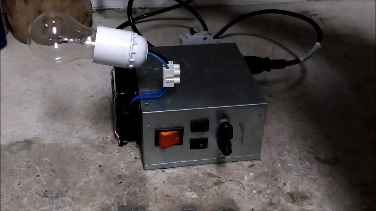
Arc welder triac power controller (Pulsetrain triggering circuit) YouTube
The Triac is most commonly used semiconductor device for switching and power control of AC systems as the triac can be switched "ON" by either a positive or negative Gate pulse, regardless of the polarity of the AC supply at that time.
TDA1023T_1323338.PDF Datasheet Download
A power controller device which uses a voltage-to-frequency converter in conjunction with a zero crossing detector to linearly and proportionally control AC power being supplied to a load. The output of the voltage-to frequency converter controls the "reset" input of a R-S flip flop, while an "0" crossing detector controls the "set" input.
Triac Triggering Circuit YouTube
1 Triggering methods 1.1 Triggering with synchronization on the TRIAC voltage The triggering circuit with synchronization across the TRIAC (See Figure 1 and Figure 2) turns on the component at an angle after the current drops to zero, such that β = ω · Tr. Time Tr is defined by the time constant (P + Rt)C. ω = 2 · · f with f = mains frequency. π
PPT TRIAC PowerPoint Presentation, free download ID4060409
The is a bipolar integrated circuit for controlling triacs in a proportional time or burst firing mode. Permitting precise temperature control of heating equipment it is especially suited to the control of panel heaters. It generates positive-going trigger pulses but complies with regulations regarding mains waveform distortion and RF interference.
RC Triggering Circuit of SCR Multisim Live
What is Time-Proportional Phase Control using Triacs or Thyristors? It is a system in which the triac is triggered with calculated lengths of PWM pulses allowing the triac to conduct intermittently for specific lengths of the mains 50/60 Hz frequency, as determined by the PWM pulse positions and time periods.
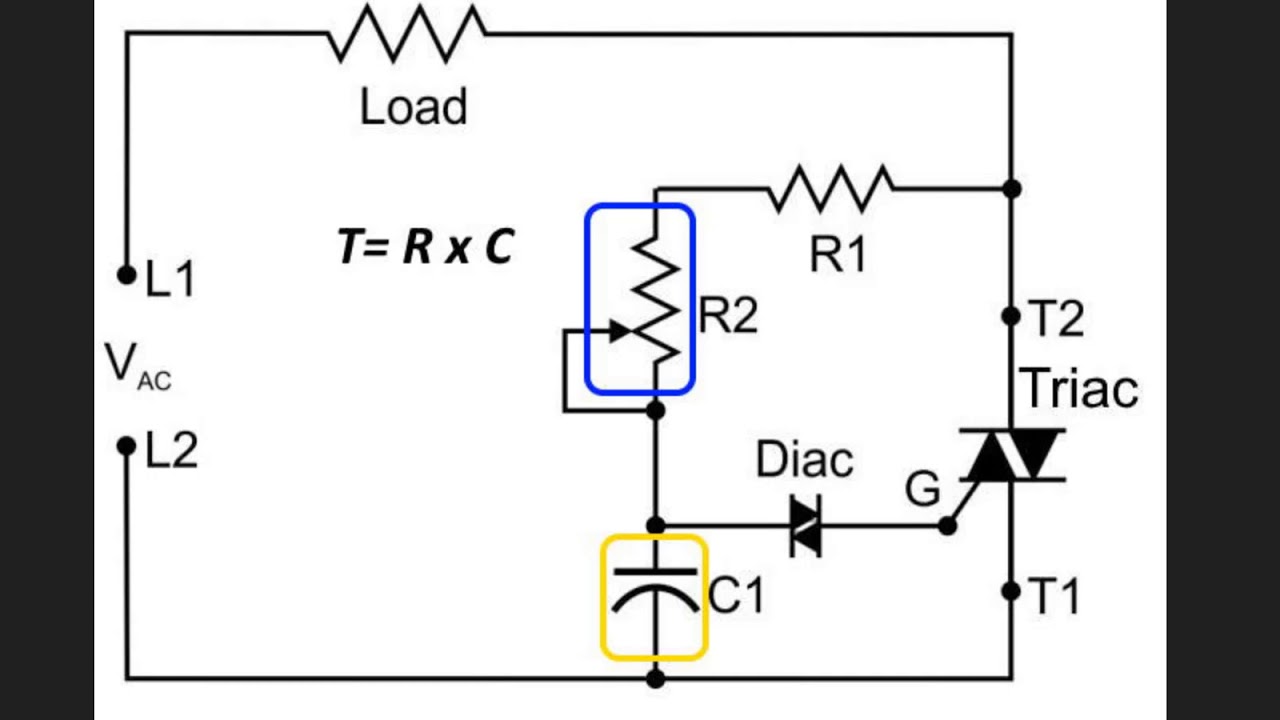
TRIAC triggering circuit using DIAC Circuit Analysis YouTube
In a synchronous triac switching, the switching periods consistently arrive on at the same moment for each AC half-cycle (typically right after the zero-crossing period) and therefore produce negligible RFI. All the circuits presented in this article use asynchronous power switching.
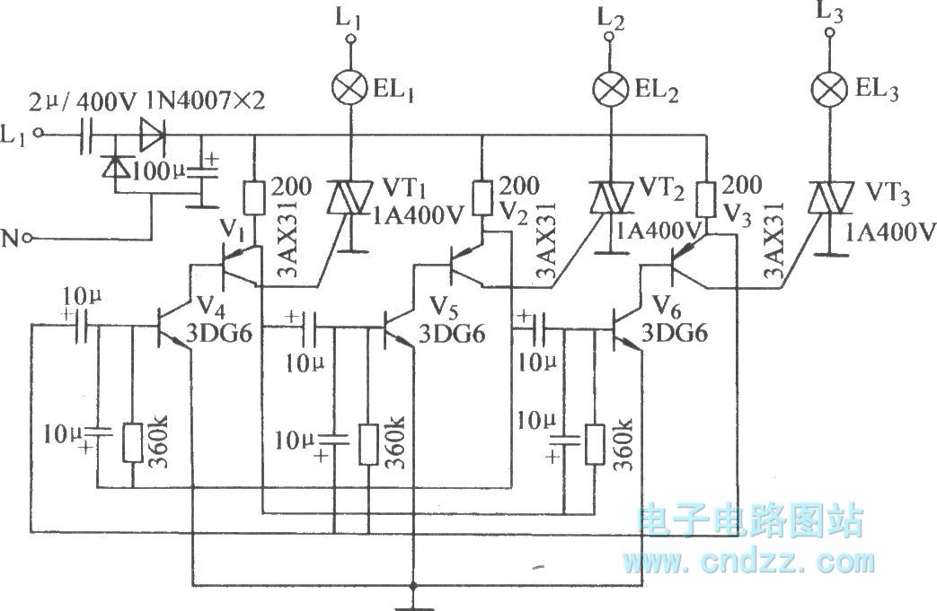
Threetube astable triggering TRIAC circuit Basic_Circuit Circuit Diagram
The IES5528 Phase Control and General Purpose Triac Triggering IC is a bipolar integrated circuit that outputs negative gate pulses for triggering a triac. Depending on the control circuit, it functions as a 0 ° to 180 ° phase controller, or zero crossing switch. The external configurability of the IES5528 makes it suitable for a wide
triac Firing angle control circuit
This is basically implemented through a couple of methods: Phase control and zero voltage switching. Phase control application is normally suitable for loads like light dimmers, electric motors, voltage and current regulation techniques.
triac Firing angle control circuit
1 If you want to use phase-angle control you will need to detect zero-cross. If the thermal time-constant of your load is of the order of several seconds then you can use time proportional control. Have a look at my Opto-triacs, solid-state relays (SSR), zero-cross and how they work and see which solution you want.

Implement an ACswitch triggering circuit using an optical Triac EE Times
The use of pulse transformers in triac triggering circuits offers many advantages: Galvanic insulation between the power and gate drive circuit (a few kV). Gate drive circuit with a few components. Choice of the gate current polarity (triggering in the 2nd and 3rd quadrants for SNUBBERLESS triacs).

AC power control using Diac and Triac YouTube
Proportional-control triac triggering circuit May 1991: TDA1024: 617Kb / 15P: A MAIN-ZERO TRIAC-TRIGGERING CIRCUIT jUNE 1976: More results. Similar Description - TDA1029: Manufacturer: Part # Datasheet: Description: Maxim Integrated Produc. MAX1640: 287Kb / 12P: Adjustable-Output, Switch-Mode Current Sources with Synchronous Rectifier
