Utv Led Turn Signal Wiring Diagram Wiring Diagram
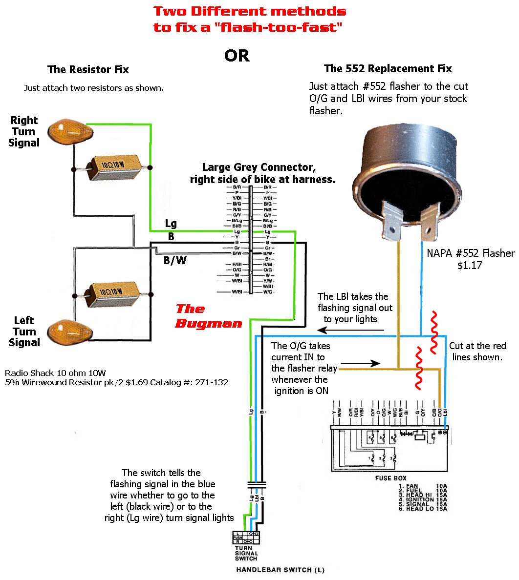
You can visually inspect them by looking into the front fairing, to the sides of the headlights. Right side - Green wire (blinker) and B/W (ground) Left side - Solid black wire (blinker) and B/W (ground) The writing is pretty straightforward with the posi tap products.

Liberty Wire Motorcycle Led Turn Signal Wiring Diagram 4
The turn signal switch is designed for ease of use and convenience. It typically has a lever that can be easily manipulated without the driver needing to move their hands from the steering wheel. The lever can be easily pushed up or down to indicate the desired direction of turn.
everlasting turn signal switch wiring
American Autowire Universal and Classic Update Kit Bolt On Turn Signal Switch wiring instructions.(updated)
1998 rav4 wiring diagram
1.8K 94K views 1 year ago Automotive Wiring How-To's This is how I would wire an LED turn signal indicator circuit without using relays. Some people also call these lights directionals or.
Universal Turn Signal Wiring Diagram
A Guide to Wiring Your LED Turn Signals Written by Doityourself Staff on Sep 18, 2010 Reviewed by H.R. Helm on Jun 26, 2023 1-6 hours • Intermediate • 0-500 Many new cars on the market today make use ofLED turn signals.
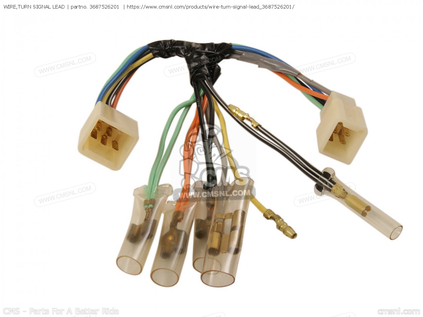
WIRE,TURN SIGNAL LEAD for RV90 1977 (B) USA (E03) order at CMSNL
How a wireless switch works. A wireless switch works like a remote or a smart device to control an outlet or light fixture—except that it allows you to mount a switch on the wall. A receiver is.
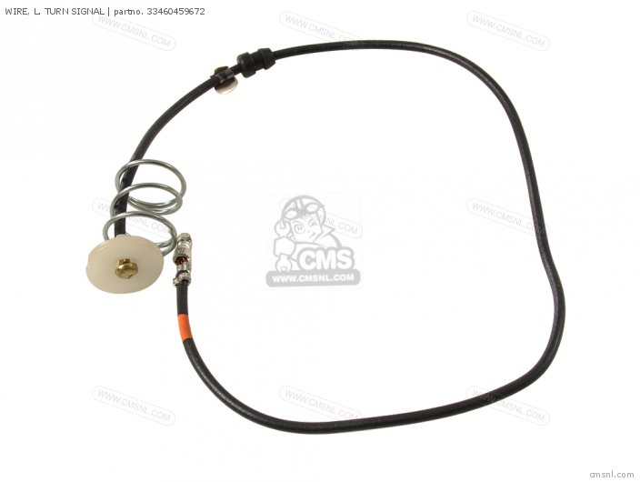
WIRE, L. TURN SIGNAL for CB250RS 1980 (A) ENGLAND order at CMSNL
2.1K Share 110K views 1 year ago Automotive Wiring How-To's In this video we wire a turn signal, brake light, parking light and hazard light switch (4-way flasher) circuit. I use the.

Wiring Diagram For 7 Wire Turn Signal Switches Replacement Youtube
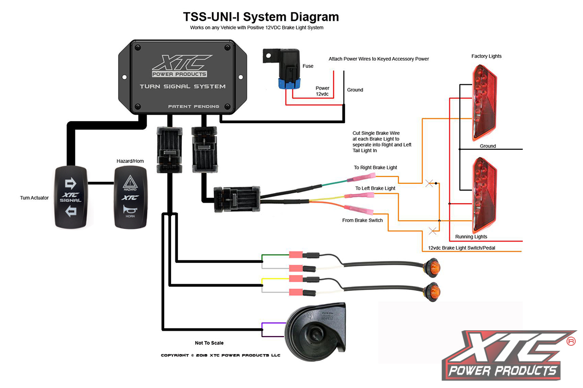
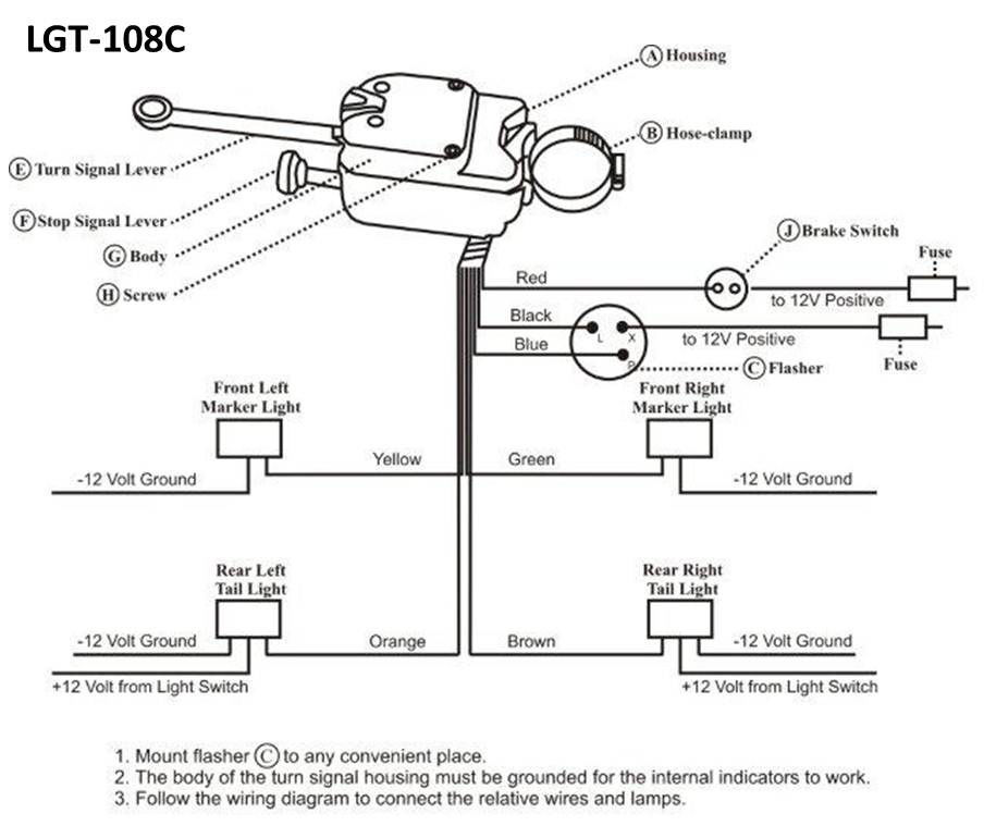
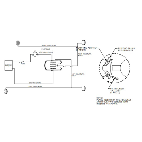
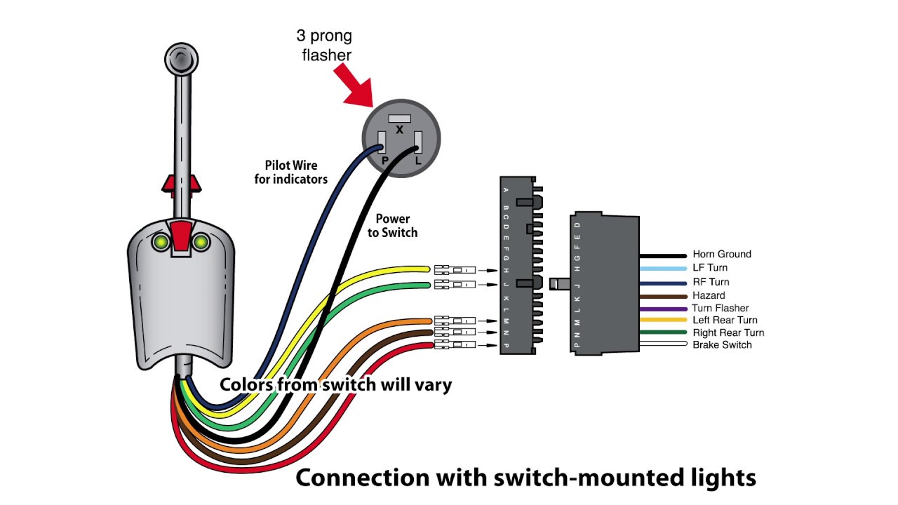
6. DO run new wires from the gray wire on the Signal Stat to your LR stop light bulb. 7. DO run new wire from the black wire on the Signal Stat to your RR stop light bulb. 8. Be sure to connect the flasher as per the sketch. Power to the X terminal, Blue wire to the F terminal and Yellow wire to the L terminal. L = load, F = flasher. 9.
Load Wiring 7 Wire Turn Signal Switch Wiring Diagram
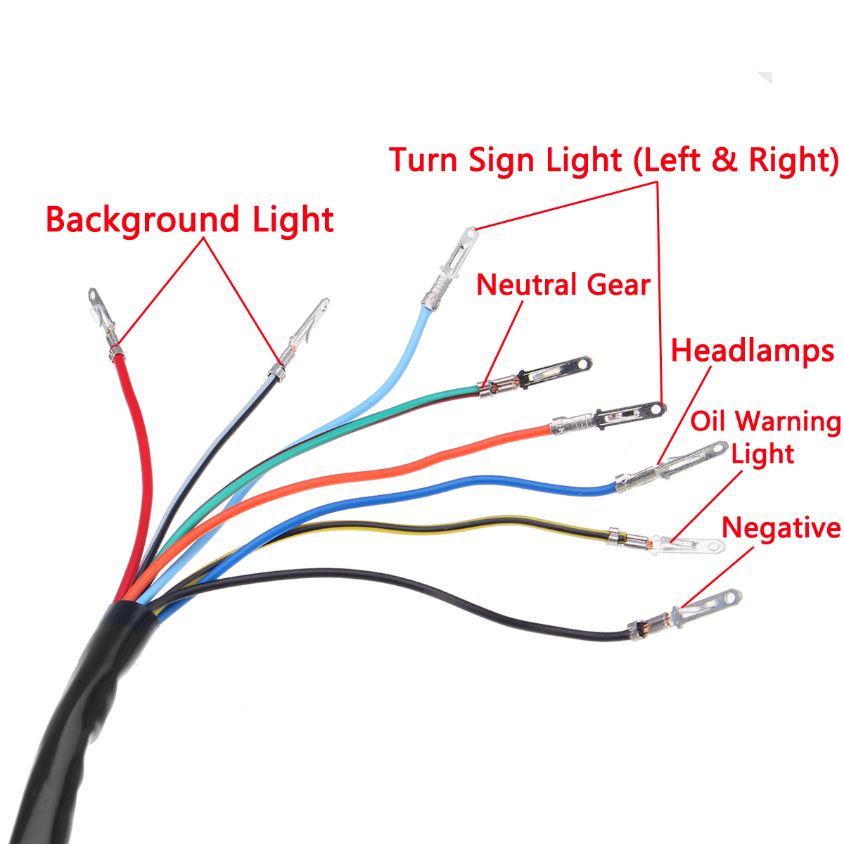
Look at the wire colors on each turn signal socket. The common wire is usually the same on both sides of the vehicle, as well as the position light wire color. But the turn signal circuit wire color is typically different on the left than it is on the right. Those are the wires that you'll attach one side of the load equalizer to. The other.
Brake Light Turn Signal Wiring Diagram Cadician's Blog
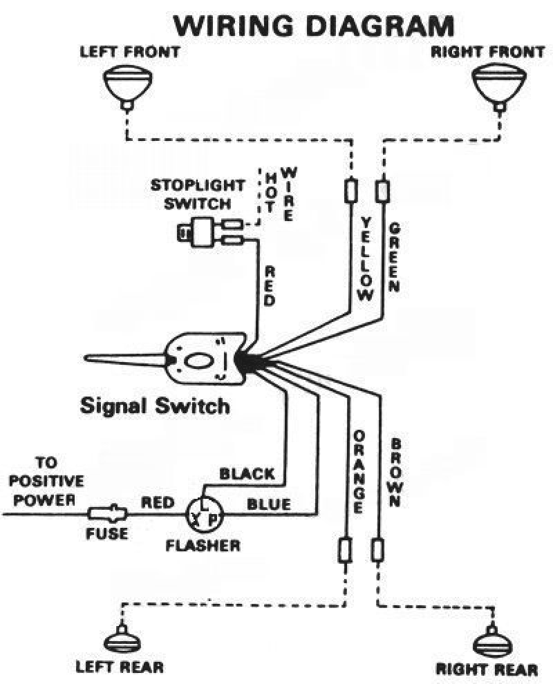
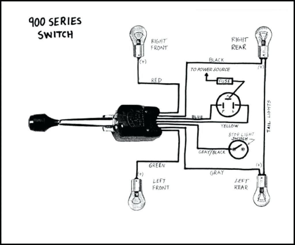
The 3-wire turn signal wiring diagram makes it easy to understand the connection between the switch and the lights. It also shows how the power is routed and the color of the wires that are used. This information is invaluable for anyone who is installing a new system or replacing an existing one. With a 3-wire turn signal wiring diagram, it is.
Signal Light Wiring
A turn signal relay (also known as a flasher relay) is the electronic device that controls your car's turn signal lights. A turn signal relay (also known as a flasher relay) is the electronic device that controls your car's turn signal lights. The clicking sound when you activate your turn signals usually comes from the turn signal relay.

Signal Stat 900 Turn Wiring Diagram Wiring Diagram
This wire will come from the turn flasher ('P' terminal on a three wire flasher). 12. Shift indicator light (some 'automatic' columns). Identifying the wires. Now let's get the meat of it. If you have fewer than six wires out of the switch, you have a turn-only switch and it isn't connected to the brake lights.
Vsm 900 Turn Signal Wiring Diagram
September 1, 2022 FACTS CHECKED BY Jose George Most drivers probably think turning signals is as easy as pushing a lever up or down to make them flash. However, there is some nifty technology at play. This article will teach you the knowledge behind and how to wire a turn signal flasher. Table of Contents What is a Turn Signal Flasher?

Turn Signal Wiring Diagram
When installing a turn signal relay, it's important to follow the wiring diagram carefully. This diagram shows how all the components are connected and which wires go where. Pay close attention to the colors of the wires, as well as the type of relay being used in order to ensure you're making the right connections.
vsm 900 turn signal switch wiring diagram
The Wiring - How Turn Signals Work | HowStuffWorks How Turn Signals Work Prev NEXT By: Karim Nice | Updated: Feb 9, 2021 The Wiring Let's take a look at how the turn-signal circuit is hooked up. The turn-signal circuit gets power when the ignition key is on. The power goes through a fuse panel into the thermal flasher.
19621972 All Makes All Models Parts MD6401 196272 ABody Turn
1. Use a factory switch. 2. Use an aftermarket switch. 3. Make your own switch system. (It's easy!) Factory switch Most of you will have a hotrod that uses a steering column that has a turn signal switch built in. What you need to do is find the wiring diagram for the vehicle the column came from. Just find it on the internet.
