Cmc Tilt And Trim Wiring Diagram Collection
Re: yamaha tilt,trim gauge wiring. Re: yamaha tilt,trim gauge wiring. the 5V comes from the yamaha trim guage, the pink wire picks off a voltage as the wiper moves between the 5V reference end of the resitor to ground. thats why I dont think teleflex ever made a gauge for it.
instead of using a variable resistor for the gauge sensor they.

Mercury Outboard Tilt And Trim Wiring Diagram Images and Photos finder
By Ayesha Nabilla | July 28, 2022 0 Comment The three wire tilt and trim wiring diagrams are essential for any boat owner who needs to get their motor up and running. By connecting the right wires, boats can be made to run faster, smoother, and with a greater range of motion.

Mercury Outboard Tilt Wiring Diagram
Sierra Marine 18 6823 Harness Converts 3 Wire To 2 For Tilt Trim Motor. New Wiring Harness Convert 3 Wire Tilt Trim Motor To 2 30 Amp Fuse Relays. Common Outboard Motor Trim And Tilt System Wiring Diagrams Mastertech Marine. I Have A 1981 Outboard With Power Trim And Tilt When You Press The On Solenoid Only Clicks Replaced.
Mercruiser Tilt Trim Wiring Diagram Wiring Diagram Schemas
Question from a fellow boater.

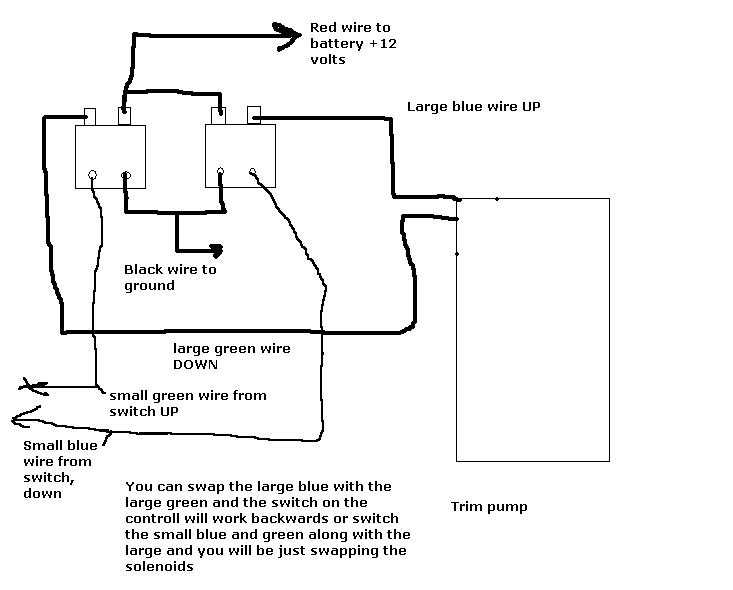
Wiring Diagram For 3 Button Single Solenoid Trim Pump For Mercruiser
#1 Bought a new trim motor for my 1985 Mercury 150. Was a 3 wire motor removed from tilt and trim system. New motor is a 2 wire system, did not come with any wiring diagrams at all, having a hard time finding a wriing diagram to show how it showed by wired if using the 2 original up and down solinoids from the 3 wire system.
power trim wiring diagram
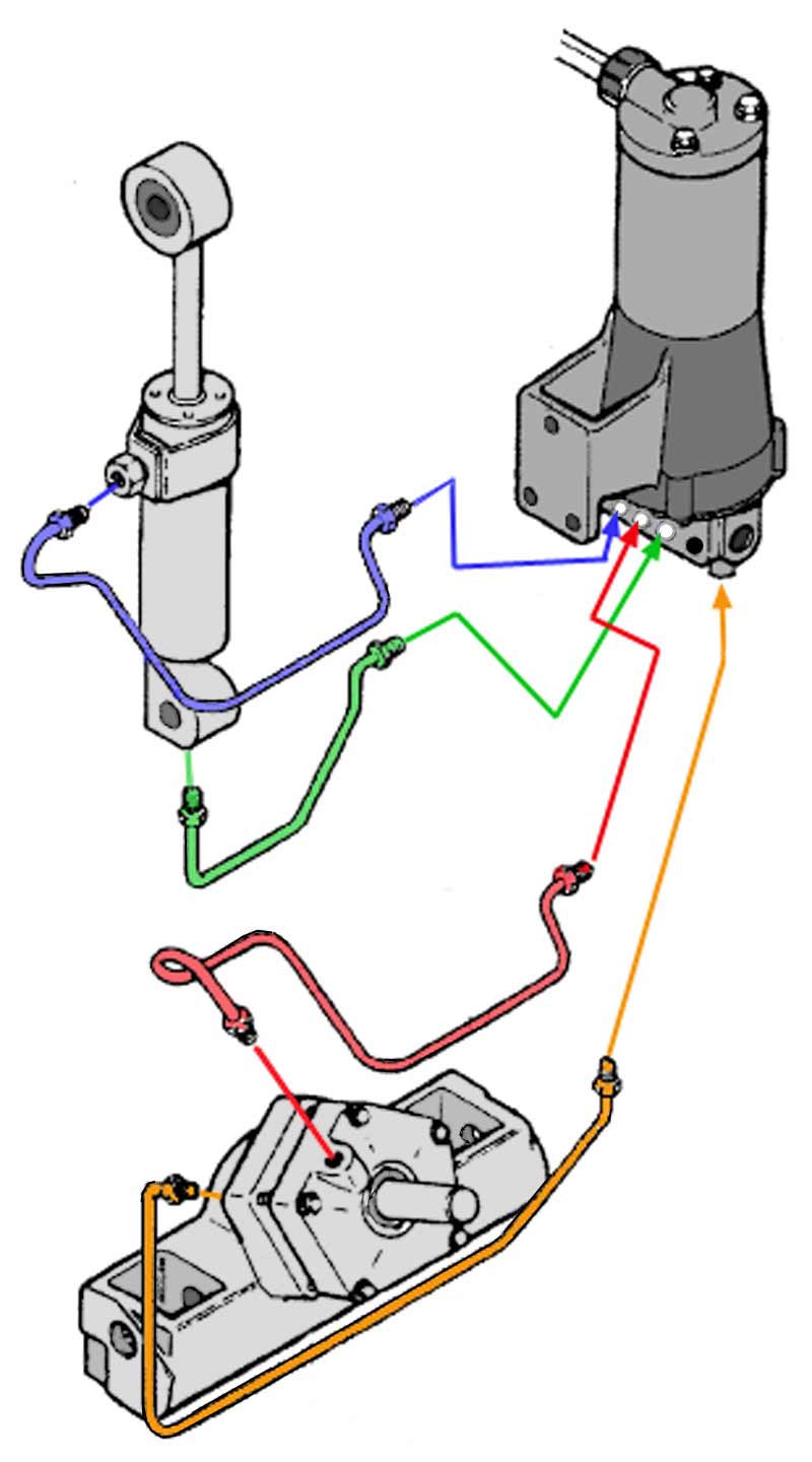
This MerCruiser power trim and tilt system is electro-hydraulically operated. Its electrical sub-system consists of a power trim control panel or handle, a pump motor and a trim limit switch, with connecting wiring. Some models may also be equipped with a trim indicator sender. Figure 1 shows a typical system. The hydraulic sub-system contains.
Trim Limit Switch Wiring Diagram Organicled
#1 I actually have a 1990 CMC PL-65 jack plate that uses the same motor (a prestolite HYB 5001) and need to get a diagram, or a pre made wiring harness. The original Johnson number is a 172850 or 173596. I have the replacement motor threw API, # PT 114N. I need a way to get this wired up correctly. Any help is greatly appreceated! C Chris1956

[DIAGRAM] Mercruiser Tilt Trim Diagram
Are you looking for a reliable way to wire up your boat's tilt and trim? If so, you should consider taking a look at 3 wire tilt and trim wiring diagrams. Wiring diagrams are essential tools for installation, maintenance, and troubleshooting of electrical systems. Tilt and trim motors are a critical component in the operation of any boat.

Evinrude Power Tilt Trim Wiring Diagram Bestn
Discover the wiring diagram for the Mercruiser tilt trim system. Learn how the components are connected and how to troubleshoot any electrical issues.. It is connected to the tilt trim motor and uses hydraulic fluid to transfer the power and control the movement of the outdrive. The pump is typically connected to a reservoir that holds the.

trim sender wiring diagram
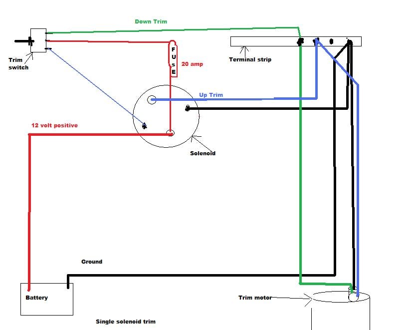
The next step is to connect the power and ground wires. Connect the power wire to the positive connection on the motor, and the ground wire to the negative connection. It is important to make sure that the connections are secure and that you have the correct polarity, as this will help to ensure that the motor runs properly. Step 3: Connect the.
78 Evinrude 3 Wire Tilt/Trim Wiring Page 1 iboats Boating Forums
The 3 wire motor has a "Black", "Blue", and a "Green wire. Battery negative (-) connects to the black wire… Battery positive (+) connects to either the "Blue" or the "Green" wire to have the motor run in one direction or the other. The 2 wire (One "Green" wire, One "Blue" wire) unit incorporates a complex relay setup for both the up and down mode.
3 Wire Tilt Trim Diagram
#1 I had a 77 140hp motor with PTT, replaced with 91 60hp. My question is how to connect the wiring, as it appears that the lead from the relay box had 3 wires, red, blue, green, but the new motor only has blue and green.

My trim up doesn't work without jumping the hot wire. What should I do?
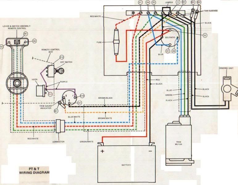
COMPANY POLICIES. GENERAL TRIM & TILT SYSTEM WIRING. CHRYSLER-FORCE. Trim Systems with 2-wire Motor and Relays. JOHNSON EVINRUDE. Trim & Tilt 1987 - UP (RELAY & 2-WIRE MOTOR TYPE) 2-Wire Motor Trim & Tilt DIFFERENT VIEW (COLORS MAY VARY) Typical Surface Mount Remote control Wiring UP TO 1995 ONLY.

mercruiser trim motor wiring
For any boat enthusiast, a 3 wire tilt and trim wiring diagram is an essential tool. Knowing how to properly wire the tilt and trim system on your boat is crucial for a safe and reliable power system.

[DIAGRAM] Mercruiser Tilt Trim Diagram
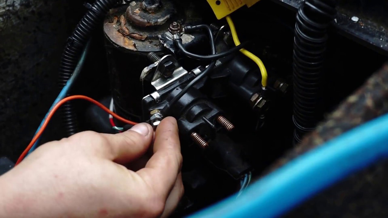
Not sure if your trim motor is working? Follow these simple steps to know for sure. Read more, here: https://bit.ly/3e4N1sPThis test will work for any 12-vol.

Mercury Outboard Motor Tilt Trim Wiring Diagram Wiring Draw And Schematic
A 3 wire tilt trim motor wiring diagram typically consists of three lines, one for each of the three wires. Each line represents a wire, with the first representing the positive wire, the second the negative wire, and the third the ground wire.
